- 您现在的位置:买卖IC网 > Sheet目录346 > NCP5007SNT1 (ON Semiconductor)IC LED DRIVR WHT COMPACT 5TSOP
�� �
�
�NCP5007�
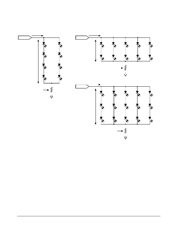
�Typical� LEDs� Load� Mapping�
�Since� the� output� power� is� battery� limited� (see� Figure� 5),�
�one� can� arrange� the� LEDs� in� a� variety� of� different�
�50� mA�
�configurations.� Powering� ten� LEDs� can� be� achieved� by� a�
�series/parallel� combination� as� depicted� in� Figure� 31.�
�75� mA�
�Load�
�Load�
�D1�
�LED�
�D5�
�LED�
�D1�
�LED�
�D3�
�LED�
�D5�
�LED�
�D7�
�LED�
�D9�
�LED�
�D2�
�D6�
�LED�
�LED�
�D2�
�LED�
�D4�
�LED�
�D6�
�LED�
�D8�
�LED�
�D10�
�LED�
�D3�
�D7�
�LED�
�D4�
�LED�
�LED�
�D8�
�LED�
�Sense�
�Resistor�
�R1�
�2.7� W�
�GND�
�60� mA�
�Sense�
�Resistor�
�R1�
�3.9� W�
�Load�
�D1�
�LED�
�D4�
�LED�
�D7�
�LED�
�D10�
�LED�
�D13�
�LED�
�GND�
�D2�
�LED�
�D5�
�LED�
�D8�
�LED�
�D11�
�LED�
�D14�
�LED�
�Test� conditions:� V� bat� =� 3.6� V�
�L� out� =� 22� m� H�
�C� out� =� 1.0� m� F�
�D3�
�LED�
�D6�
�LED�
�D9�
�LED�
�D12�
�LED�
�D15�
�LED�
�Sense�
�Resistor�
�R1�
�3.3� W�
�GND�
�Figure� 31.� Examples� of� Possible� LED� Arrangements�
�http://onsemi.com�
�17�
�发布紧急采购,3分钟左右您将得到回复。
相关PDF资料
NCP5008DMR2
IC LED DRVR WHT BCKLT 10MICROSMD
NCP5010FCT1G
IC LED DRVR WHT BCKLT 8-FLIPCHIP
NCP5021MUTXG
IC WHITE LED DVR HV AMB 16-UQFN
NCP5050MTTXG
IC LED DRIVR PHOTO FLASH 10-WDFN
NCP5111DR2G
IC DRIVER HI/LOW SIDE HV 8-SOIC
NCP5304DR2G
IC DRIVER HI/LOW SIDE HV 8-SOIC
NCP5355DG
IC DRVR SYNC BUCK MOSF 12A 8SOIC
NCP5359ADR2G
IC MOSFET GATE DVR DUAL 8-SOIC
相关代理商/技术参数
NCP5007SNT1G
功能描述:LED照明驱动器 White LED Backlight Boost RoHS:否 制造商:STMicroelectronics 输入电压:11.5 V to 23 V 工作频率: 最大电源电流:1.7 mA 输出电流: 最大工作温度: 安装风格:SMD/SMT 封装 / 箱体:SO-16N
NCP5008
制造商:ONSEMI 制造商全称:ON Semiconductor 功能描述:AC-DC Offline Switching Controllers/Regulators
NCP5008/D
制造商:ONSEMI 制造商全称:ON Semiconductor 功能描述:White LED Driver
NCP5008_06
制造商:ONSEMI 制造商全称:ON Semiconductor 功能描述:Backlight LED Boost Driver
NCP5008DMR2
功能描述:LED照明驱动器 15V Output Max LED RoHS:否 制造商:STMicroelectronics 输入电压:11.5 V to 23 V 工作频率: 最大电源电流:1.7 mA 输出电流: 最大工作温度: 安装风格:SMD/SMT 封装 / 箱体:SO-16N
NCP5008DMR2G
功能描述:LED照明驱动器 15V Output Max LED Backlight RoHS:否 制造商:STMicroelectronics 输入电压:11.5 V to 23 V 工作频率: 最大电源电流:1.7 mA 输出电流: 最大工作温度: 安装风格:SMD/SMT 封装 / 箱体:SO-16N
NCP5009
制造商:ONSEMI 制造商全称:ON Semiconductor 功能描述:Backlight LED Boost Driver
NCP5009DMR2
功能描述:IC LED DRVR WHT BCKLT 10MICROSMD RoHS:否 类别:集成电路 (IC) >> PMIC - LED 驱动器 系列:- 标准包装:1 系列:- 恒定电流:- 恒定电压:- 拓扑:PWM,切换式电容器(充电泵) 输出数:1 内部驱动器:是 类型 - 主要:背光 类型 - 次要:白色 LED 频率:642kHz 电源电压:2.7 V ~ 5.5 V 输出电压:5V 安装类型:表面贴装 封装/外壳:10-VFDFN 裸露焊盘 供应商设备封装:10-VSON 包装:剪切带 (CT) 工作温度:-30°C ~ 85°C 产品目录页面:1371 (CN2011-ZH PDF) 其它名称:BD1603NUV-E2CT